Touch Sensor and Plasma Torch Height Control Configuration for Mach4 Ver.2
Posted:
June 14, 2023
Touch Sensor and Plasma Torch Height Control Configuration for Mach4
Overview:
There are two ways of commanding the plasma cutting sequence. You could command all the actions using gcode commands (M62/M63 as torch on/off, G31 for probing, and G4 for piercing delays) or you could set all the operating parameters and just command the plasma using the 2003/M2005 macros. These instructions will configure the system to use it both ways.
M2003 Macro performs the following actions:
- Probes or moves down the Z axis to the "Z Min. height" position that is set in the DRO for this value and the feed that is set in "Probing FR".
- Set the current position to be the new Z = Zero considering the Z Offset if a Floating Head is used.
- Moves the Z up at max velocity to the piercing position or DRO = Pierce Height.
- Turn on the Torch.
- Wait for Pierce time or DRO = Pierce Delay.
- Moves the Z up at max velocity to the cut position or DRO = Cut Height.
- Activate THC.
M2005 Macro performs the following actions:
- Turns the torch off.
- Deactivates the THC.
- Moves the Z axis at max speed to the position where it would be safe to move at max velocity to the next cutting position. This is DRO =Z Top.
- The screen holds the new DRO values and also has the code that will enable the probe while the system is probing.
Used software: Mach4 4.2.0.5036.
https://www.machsupport.com/wp-content/uploads/2014/04/Mach4Hobby_Installer-4.2.0.5036.exe
ESS Plugin Mach4: ESS v284.
https://warp9td.com/files/Plugins/ESS/Mach4/ESS_Mach4_v284.zip
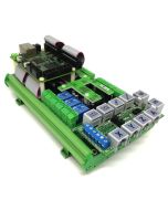
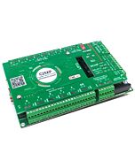
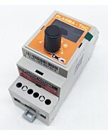
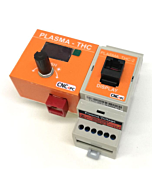
Hardware Used:
THC-1 or THC-2, PTS-1
Start by making a backup of the existing installation:
Make a backup of the configuration and file installation, we recommend creating a backup of the current installation by right-clicking in the current installation folder and zipping it.

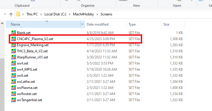
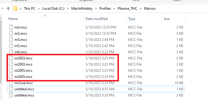
Download and install the new screen and macro files: Download the compressed file containing the macros and screen that work with the macros: https://www.cnc4pc.com/pub/media/productattachments/files/M4_CNC4PC_Plasma_V2.zip You will need to install the screen found in the download folder and place the macro in the macros directory for the profile folder. |
Make a backup of the original M2003 and M2005 macros by zipping them into the same folder, just so you may have access to the original macros if you need to revert the installation later: |
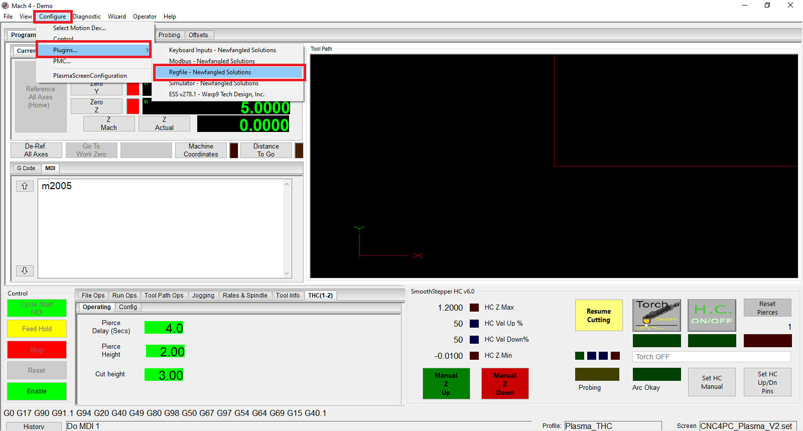
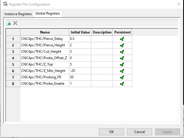
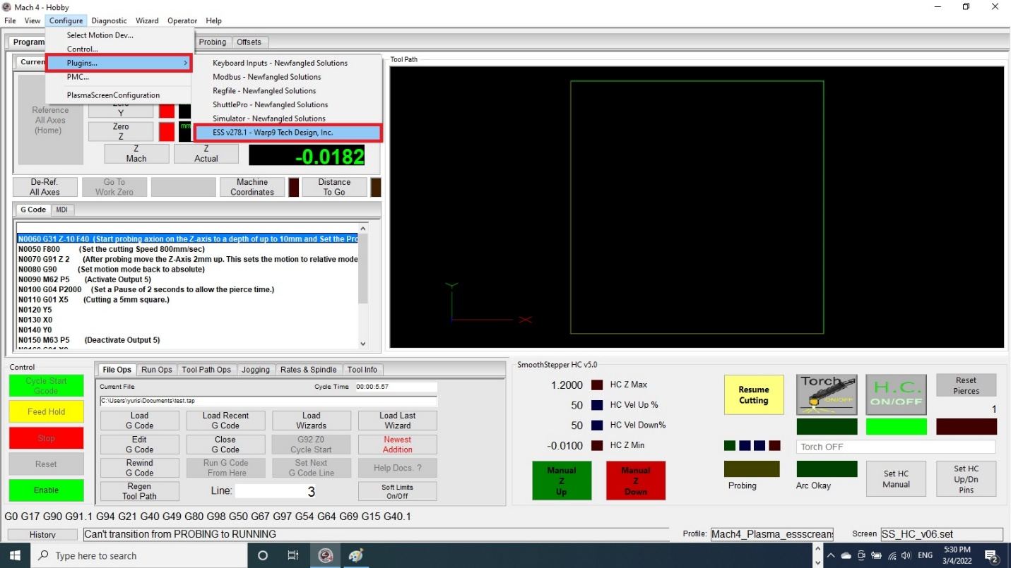
Configure/Plugin/Regfile: |
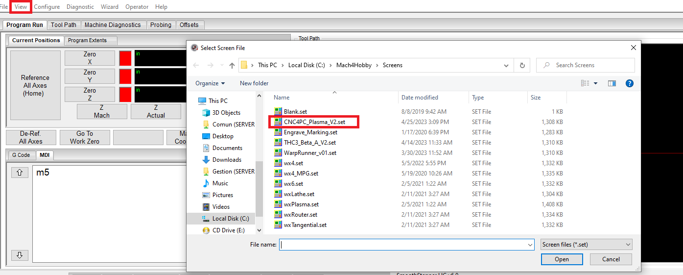
View/Load Screen: |
| Apply Changes, Save Settings, and Restart MACH4 for all the changes to take effect. |
On the Main Screen, you need to set the piercing parameters: |
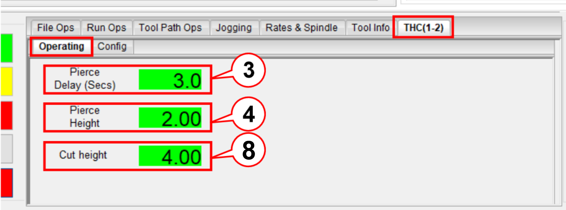
3. Set the THC delay or Piercing Time. 4. Set the height at which you want to start cutting or do the initial pierce. 8. Cut height |
On the Main Screen, you need to set the piercing parameters: |
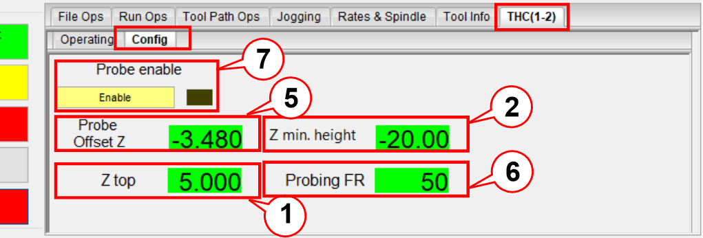
1. Set Z_Top which is the safe position from which you can do a rapid motion to the new cutting position. 2. Set how low you want the Z-axis to go while probing or touching the plate. 5. Set the OFF SET_Z. 6. Set the Probing FR. 7. Set the Probe enable. |

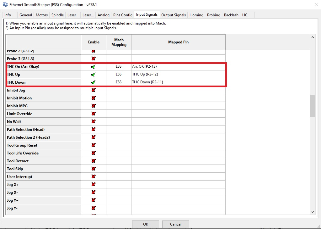
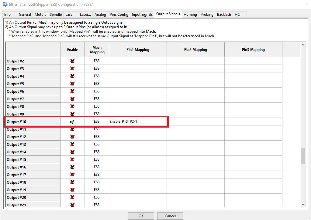
Probe pin configuration. This is the pin used to sense the probing action. This pin will go high when the probe touches the plate. If using a floating head where the z-axis will need to travel to the switch position, you need to set the Z offset. |


Testing and Troubleshooting Considerations: Test Probing with a PTS-1 or Floating head:
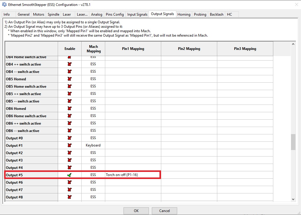
Test that the Touch Relays Starts/Stops the Plasma M62 should start the plasma and M63 should stop it. Observe action on the screen LEDs, Output pins of the breakout board, relay, and plasma cutter. Test THC action:
|

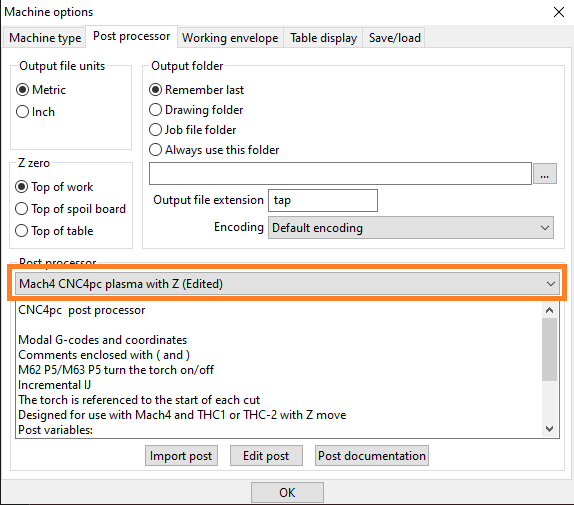
Setting up the Post Processor.
STEP 1:
Load the postprocessor to be used: Select the "MACH4 CNC4pc plasma with Z" postprocessor in Options/Machine. |
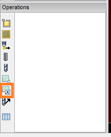
STEP 2:
Click on "Set a post-processor variable". |
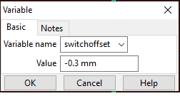
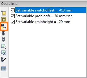
STEP 3:
Enter the values of the variables to be used on probing: Steps 2 and 3 may need to be repeated for each variable. these can be: switchoffset (offset of the floating head switch), zminheight (how low the Z axis goes while probing), and probingfr (Velocity at which probing will be executed). |
STEP 4:
Create Cut Feature: After having entered all the variables, we proceed to do the cutting operation. |
This instruction is the update for these old instructions.
Related Products
Comment(s)